Model NO.: EN-BW-1300-300
Max Pressure: 25MPa
Max Flux: 200L/Min
Trademark: EN-SOURCE
Transport Package: Steel Wire.
Specification: 300-1300mm
Origin: China, Zhejiang
HS Code: 85041900
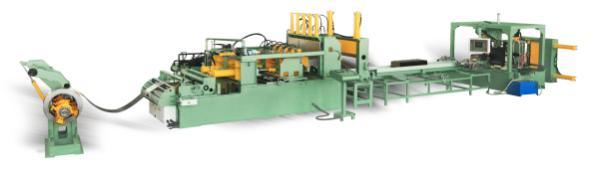
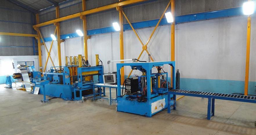
I General Layout for Transformer Corrugation Fin Production Line (fin forming, fin seam&edges welding, reinforcing rod welding, spot welding, vertical bending and tank assembling)
Build up of Transformer Corrugated Fin Production Line as the Drawings Shown
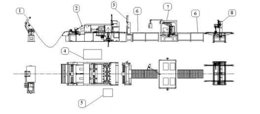
1. Transformer Corrugated Fin Forming Unit
1 Hydraulic Automatic Decoiler Machine
2 Automatic Transformer Corrugated Fin Forming Machine
3 Hydraulics Plate Shearing and Hemming Machine
4 Hydraulic System
5 Electrical Control System
2. Transformer Corrugated Fin Seam Welding Unit
6 Roller Conveyor
7 Corrugated Fin Automatic Welding Machine
3. Transformer Corrugated Fin Spot Welding Unit
8 Spot Welding Machine for Fin Embossment
4. Transformer Corrugated Fin Vertical Bending Unit
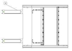
9 Hydraulic Vertical Bending Machine
5. Corrugated Tank Assembly Unit
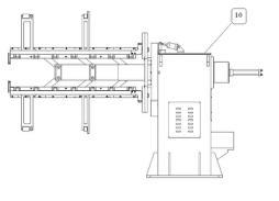
10 Tank Assembly Manipulator for Corrugated Tanks
General Introduction of Transformer Corrugation Fin Production Line
The corrugated fin production line is special equipment for manufacturing sealed and maintenance-free transformer oil tanks.
Main producing process: decoil the material, form plate corrugation, shear and hem corrugated plate, convey and weld corrugation ends edges, weld reinforcing rod, weld fin embossment, bend the finished corrugated fin, assembly corrugated steel tank.
Main Technical Parameters of Transformer Corrugated Fin Production Line
1. Width of corrugation: 300~1300mm
2. Thickness of steel sheet: 0.5-1.75mm
3. Length of formed sheet: >=290mm
4. Height of corrugation: 50-400mm
5. Corrugation pitch: >=40mm
6. Corrugation pitch accuracy: ±0.25mm
7. Corrugation inner gap: 6mm
8. Max. Pressure: 25MPa
9. Max. Flux: 200L/min
II Equipment Description
1. Description of Necessary Machine Unit
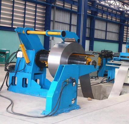
(1) Hydraulic Automatic Decoiler Machine
1.1 Introduction
The base frame of the decoiler is made from welded steel construction. The expandable mandrel is mounted on roller bearings, and its expansion and retraction are controlled hydraulically. When the steel sheet is automatically fed, a hydraulic motor on the mandrel assists in the decoiling and partial rewinding of the coil. A photoelectrical device with two switches detects the sheet between the decoiler and the corrugation former to control the feeding process.
1.2 Parameters of Our Hydraulic Automatic Decoiler Machine
1) Hydraulic pressure: 16MPa
2) Coil inner diameter: Min 470mm, Max 520mm
3) Max. External diameter of steel coil: 1200mm
4) Coil width: Max. 1300mm
5) Coil weight: Max. 10 tons (with inclined support structure)
(2) Transformer Corrugated Fin Forming Machine
2.1 Introduction
The corrugation former consists of a steel-welded base, a 2-roll feeder, movable forming mold, and both movable and fixed forming pressboards. It is used to automatically form steel corrugations. The machine operates based on the theory of corrugation extrusion and is controlled by a high-precision servo system. Hydraulic oil is supplied by the hydraulic station. The control system is independent from the welding unit. Two quenched pressing bars on each forming pressboard are used to press the ends of the corrugation, and their positions can be adjusted according to the width of the steel sheet. Reinforcement slots (embossments) can be formed upon customer request.
2.2 Parameters of Our Transformer Corrugated Fin Forming Machine
1) Plate width: 300mm-1300mm (according to customer's needs)
2) Corrugation height: 50mm-400mm
3) Corrugation pitch: >=40mm
4) Plate thickness: 0.5mm-1.75mm
5) Forming speed: 3-4fins/min
6) Power: 28KW
7) Number of pumps: 2 (two separate plunger pumps)
8) Control system: electrical, hydraulic and control board
(3) Hydraulic Plate Shearing and Hemming Machine
3.1 Performance Features of Hydraulic Plate Shearing and Hemming Machine
This device is used to shear and hem corrugated steel fins. With this hemming edge, it becomes easier to create "corrugated fin tanks" and weld different pieces of corrugated fins into a transformer tank more tightly. The machine includes a lower shearing blade and an upper movable shearing blade mounted on pillar guides. The blades are made from tool steel and can withstand over 100,000 cuts after sharpening with minimal burr. Shearing and hemming can be done manually or automatically using a feeding mechanism. The process is hydraulically driven.
3.2 Parameters of Our Hydraulic Plate Shearing and Hemming Machine
1) Shearing width: 300mm-1300mm
2) Corrugation height: <=400mm
3) Shearing thickness: <=2.0mm
4) Shearing time: 3-5 seconds/time
5) Hemming function is optional, hemming height: 20mm (can be selected from 18mm to 25mm but must be fixed)
(4) Hydraulic System
The hydraulic system consists of an oil tank, pump, motor, and regulating valves. The main hydraulic components are provided by Rexroth Company, Germany.
4.1 Parameters of Our Hydraulic Station
1) Max. Pressure: 25MPa
2) Max. Flux: 200L/min
3) Pump motor power: 28KW
4.2 Pictures of Our Hydraulic Station
(5) Electrical Control System
5.1 The electrical control system includes the main control cabinet, operation console, local operation panel, and connection wires. All relays, switches, transformers, and PLCs are installed in the main control cabinet. MITSUBISHI controllers are used to manage the production line. The sheet feeder and welding torch movement are controlled by MITSUBISHI AC Servo drive systems. SCHNEIDER monitors have been integrated as man-machine interfaces. The control console is equipped with a SCHNEIDER color touch screen, buttons, and indicator lights. Lamination shapes (like fin width, fin height, and pitch) and parameters can be easily adjusted through the SCHNEIDER color touch screen monitor. After inputting related parameters, automatic circulation operation is achieved. Local control panels located throughout the production line enable manual operation.
5.2 Pictures of Our Control System (Control Station, Control Panel)
(6) Roller Conveyor
6.1 Features of Roller Conveyor
The transport rollers are used to convey the sheared and hemmed corrugated sheets to the welding device. The roller conveyor is equipped with ball bearings for flexible conveyance without motorization.
6.2 Pictures of Roller Conveyor
(7) Corrugated Fin Automatic Welding Machine
7.1 Introduction of Our Corrugated Fin Automatic Welding Machine
The welding device is used to weld the corrugation ends edges and reinforcing rod using MAG welding mode, with the diameter of the round rod bar ranging from 6mm to 8mm. It consists of a corrugated steel sheet conveying mechanism, welding torches elevating mechanism, amplitude modulation mechanism, and one machine hand. The conveying mechanism transports the corrugated steel sheet to the correct welding position according to the welding program. Each pair of welding clamps is driven by an air cylinder via a link drive mechanism to hold and release the workpiece. The welding torches are mounted on a slide driven by a servo motor along a rolling guide via a ball screw shaft. The amplitude modulation mechanism includes two sets of welding clamps and welding torch moving mechanisms arranged on both sides of the line. The distance between the two slides is adjustable along the rolling guide with a centering lead screw. In case of missing seam welding, the machine hand is used to push the corrugated fin to the welding position, and it is driven by an air cylinder. Two sets of Panasonic Welders are installed in the line.
7.2 Specifications of the welder are as following:
1) Welding speed: Vs=0.5~1 m/min
2) Welding wire feeding speed: Vd=3.4~6 m/min
3) Electric arc voltage: 15-16V
4) Welding current: 50-60A
5) Diameter of welding wire: 0.8 mm
6) Shield gas: 85% Ar+15% CO2
7) Consumption of shield gas: 15 L/min
8) Tip length of welding wire: 7~10 mm
(8) Spot Welding Machine for Fin Embossment
8.1 General Introduction of Our Spot Welding Machine (i.e. Fin embossments spot welding machine)
This spot welding machine is used to increase the strength of reinforcement slots (embossment).
8.2 Main Units of Corrugated Fin Spot Welding Machine:
1) Conveyor
2) Centering system
3) Clamps & generators
4) Cooling system
5) Control console with computer
8.3 Parameters of Corrugated Fin Spot Welding Machine
1) With 2 spot guns.
2) Total rated power: 50KVA x 2
3) Cooling system
4) HMI control system
5) Suitable fin width: 600mm-1600mm
6) Suitable fin height: >=120mm
7) Air Source: Self provided.
8) Air pressure: 0.6Mpa (minimum)
8.4 Pictures of Corrugated Fin Spot Welding Machine
Running Machine                               Finished Products
(9) Hydraulic Vertical Bending Machine
9.1 This hydraulic vertical bending machine allows to form the 4 panels composing the complete transformer tank. Using this system, it eliminates 3 weldings, saves time in assembling and welding the tank, and reduces the risk of leakage.
9.2 Main Units of Hydraulic Vertical Bending Machine:
1) Bending system
2) Safety system for the operator
3) Hydraulic unit
4) Control panel
9.3 Main Parameters of Hydraulic Vertical Bending Machine:
1) Sheet thickness (Max.): 1.75mm
2) Panel width (Max.): 1300mm
3) Panel fin height: 50-400mm
4) Distance between panels (Min.): 60mm
5) Power: 5.5Kw
6) Hydraulic pressure: 10MPa
9.4 Pictures of Hydraulic Vertical Bending Machine:
(10) Tank Assembly Manipulator for Corrugated Tanks
10.1 Main Features of Tank Assembly Manipulator for Corrugated Tanks
Tank assembly manipulator is designed for fast and easy assembly of the top frame, tank bottom, and the four corrugated panels to make a complete tank.
10.2 Main Units of Tank Assembly Manipulator for Corrugated Tanks:
1) The base frame
2) The hydraulic expanding head
3) A small hydraulic power pack
4) 4 sets clamp arms
10.3 Specific Technical Data
1) Basic parameters of equipment:
Rated power: 4KW
Rated voltage: 380V
Rated pressure: 0.8MPa
Rated oil pressure: 3MPa
2) Tank inside dimensions:
Min (W) 285mm to 900 mm
Max (L) 600mm to 1500mm
10.4 Pictures of Tank Assembly Manipulator for Corrugated Tanks:
2. Technical Parameters of this Transformer Corrugated Fin
Â
| No. | Parameters | 800mm | 1300mm | 1600mm |
| 1 | Plate Width (W) | 300~800 mm | 300~1300 mm | 300~1600 mm |
| 2 | Plate Thickness (T) | 0.5~1.75mm | ||
| 3 | Corrugation Height (H) | 50~300mm | 50~400mm | |
| 4 | Corrugation Pitch (P) | >=45mm or >=40mm | ||
| 5 | Pitch Tolerance | ± 0.25mm | ||
| 6 | Hemming Height (R) | 20mm | ||
| 7 | Fin Gap (G) | 6mm | ||
Round Magnet,Powerful Magnets Round Magnet,High Performance Round Magnets,Super Strong Round Magnets,customizable sintered NdFeb magnets
GEILI Magnetic Industry Co., LTD , https://www.geilimagnet.com