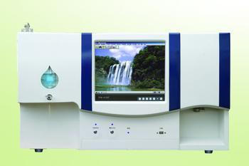
 1. Connect and power the instrument Connect the mains power socket to the mains with the power cable, and ground the instrument reliably (otherwise it will be easily disturbed and cause data fluctuations); Check if the drain hose is firmly installed (do not put the outlet of the liquid hose) In order to avoid liquid slumping, inject distilled water (reference solution) into the cuvette and turn on the instrument power switch. At this time, the instrument displays the unit name and date, accompanied by a sound, and presses the “cursorâ€. Press the key to move the cursor and enter the year, month, and day. And press the "confirm" button to end; if you do not need to modify directly press the "confirm" button to enter the sample test interface.
 Second, zero input and fullness adjustment In the daily use of the instrument, it is necessary to adjust zero and full-scale work.
The zero point generally does not need to be adjusted frequently. Each time you start up, enter the sample test interface and press the “Zero†key.
When the fullness is adjusted, adjust the channel fullness adjustment knob at the cursor position in the sample test interface so that the signal percentage is displayed as about 100.0. Press the “Full†button again and the full scale will be tracked to 100.0±0.1. Steps to adjust the fullness of other channels.
The full-scale adjustment can also be performed in the standard calibration interface. When the cursor is on the “T†display line in the target calibration interface, the “full-scale†key is pressed, and the full-scale is traced to 100.0±0.1.
Third, the sample test and print 1, in the sample test interface, the cursor default in the first channel position.
2, first add a good reference solution, adjust the zero, full scale.
3. Press the "Cursor" key to cycle through the cursors in each channel.
4. Press the number key (0-9) to call the corresponding curve (Article 0-9).
5. Discard the reference solution and add the color solution of the sample. The value shown in "C" is the percentage of the sample. The value shown in "T" is the transmittance, and "A" is the middle display. The value is the absorbance.
6. Press the "Print" number (1-4) key "Confirm" to print out the relevant parameters of the corresponding channel. Press "Print" "0" "Confirm" to print the relevant parameters of the four channels at the same time.
7. Follow the above steps to complete related measurements for other channels.
8. Press “Search†to enter the query modification interface.
9. Press the "Standard/Test" button to enter the target calibration screen.
Metal Speed Controllers,Pneumatic Push Fittings ,Push Lock Fittings ,Brass Air Fittings
Pneumatic Fittings Co., Ltd. , http://www.nbpneumaticfittings.com