In the practical application of the project, compressed air flow meters usually have several installation methods as shown in Fig. 2 [10], in which (a), (b), (c) are all three types of horizontal installation; (d) is Vertical installation of compressed air flowmeters. Different installation methods should be used for different fluids. Common liquids, gases, gases containing liquids, cryogenic gases and liquids, and liquids and gases containing traces of solid particles can be installed in (a), (c), (d); high-temperature liquids, high-temperature gases, and steam can be used. (b), (c), (d) Installation; wet saturated steam can be installed in (a), (c), (d); liquid-gas (including trace gases), liquid-solid (including trace solids) In the liquid-liquid two-phase flow, if the gas and solid phases do not exceed the measurable range, it is recommended to first install in (d). 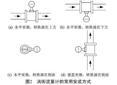
Experiments and results discussion
1.1 Experimental apparatus and process The structure of the experimental apparatus is shown in Fig. 3. The water pressure regulator tank provides a constant water pressure for the pipeline, so that the flow rate during the experiment is stable. The flow rate of the water is regulated by a regulating valve and the flow rate ranges from 2 to 20 m3. /h. The electromagnetic flow meter gives the standard flow rate of water entering the experimental section as a standard flow meter with an accuracy of 0.5%. Compressed air flowmeters are installed in the experimental pipelines in horizontal and vertical modes, respectively, and they have long enough front and rear straight pipe lengths, and other installation conditions are strictly in accordance with the requirements. The signal of the compressed air flowmeter is collected by an oscilloscope. The sampling frequency is 1000 Hz, and each set of data contains 2500 points. 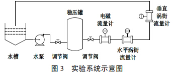
1.2 Experimental Results and Analysis The vortex street signals measured in the horizontal and vertical installation modes are respectively subjected to Fast Fourier Transform (FFT) to obtain the vortex street frequency value. Figure 4 shows the vortex street frequency and flow rate. Relationship between. As can be seen from the figure, the difference between the two is small. Then, zero-intercept least squares fitting was performed on the measured vortex street rate and flow rate, respectively, and the horizontal and vertical installed compressed air flowmeter meter coefficients were 2.5202 Hz/(m3/h) and 2.5198 Hz/(m3/), respectively. h) The relative error is less than 0.02%. It can be seen that the installation method has very little influence on the measurement of the compressed air flow meter and can be ignored. 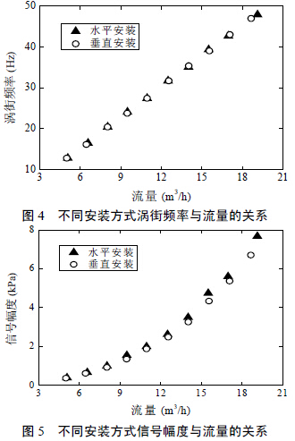
In order to further study the influence of the installation method of the compressed air flowmeter, this paper also compares the amplitude of the vortex signal in both horizontal and vertical modes. Figure 5 shows the relationship between vortex signal amplitude and flow. It can be seen that the signal amplitude and flow rate are approximately quadratic. At the same flow rate, the signal amplitudes are substantially equal. This shows the installation of the compressed air flowmeter. The effect on the signal amplitude is small, ie the energy of the vortices (proportional to the square of the amplitude) is hardly affected. However, a closer comparison shows that the signal amplitude when the compressed air flow meter is installed horizontally is slightly larger than that of the vertical installation. It can be qualitatively understood that when the compressed air flow meter is installed vertically, part of the vortex energy is dissipated due to overcoming the force of gravity. The vortex energy sensed by the compressed air flowmeter sensor becomes less, resulting in deformation at both ends (diameter increase) larger than the middle of the tube screen; in the width direction, the deformation of the middle steel pipe (diameter reduction) is greater than the steel pipe on both sides The deformation. This is mainly due to the different deformation conditions and heat dissipation of the weld in different welding areas. In the initial stage of tube panel welding, the heat dissipation is better due to the lower tube screen temperature, but the deformation of the end of the tube panel is less constrained and easily deformed; when welded to the center of the tube panel, even if the temperature rises, the deformation is affected. The constraint of the pipe is not easy to produce deformation; in the tail of the pipe screen, the temperature is high and the heat dissipation conditions are poor, the deformation constraint is small, and the most easily deformed. Figure 6 shows the deformation of the membrane wall tubes welded by a φ76×4 tube and a 6×34 flat steel tube in the same direction under the same welding specification. The diameter change rate is about 0.04%. In the width direction, there is an opposite deformation. 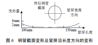
Although different welding power sources can be set to different welding specifications, in the conventional control, for the same welding torch (welding power source), the specification from arc starting to arc closing (whole welding process) is generally fixed As a result, the two ends of the tube screen are deformed (axial deformation). In engineering practice, it is often necessary to cut about 200 mm at both ends of the tube screen, wasting a lot of materials. In order to reduce welding distortion, in the control system, the specification of the welding process is regulated in real time according to the law shown in Fig.7. 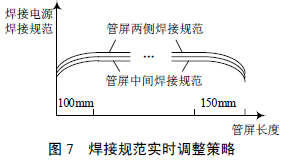
When starting arc, the temperature is low, combined with welding deformation, using a small welding power, welding to 100 mm into the stable arc section, set back to normal specifications (maximum welding power), 150 mm before the end due to poor heat dissipation conditions, The temperature rises faster, thus reducing the welding power (smaller than the arc section). In practical applications, the data is stored in the control system in the form of welding specifications and welding length, and is transferred from the control system to the welding power source when welded to the corresponding length.
Auxiliary equipment for activated carbon production includes screening equipment, dust removal equipment, packaging equipment, conveying equipment, crushing equipment and drying equipment.


If you have any questions, please contact with us directly Welcome you can visit our Factory.For inqury,Please send mail directly to us.
Supporting Activated Carbon Equipment
Activated Carbon Complete Set Of Equipment,Activated Carbon Screening Equipment,Activated Carbon Packaging Equipment,Activated Carbon Crushing Equipment
Shandong Hengyi kaifeng Machinery Co.,Ltd , https://www.xhykf.com